
Getting to Grips with Analog Design
In the final of our four-part series highlighting the shortage and importance of analog design engineering skills, we explain how it’s possible to quickly design a fully functional analog filter circuit without manually calculating component values, using complex numbers or differential equations.
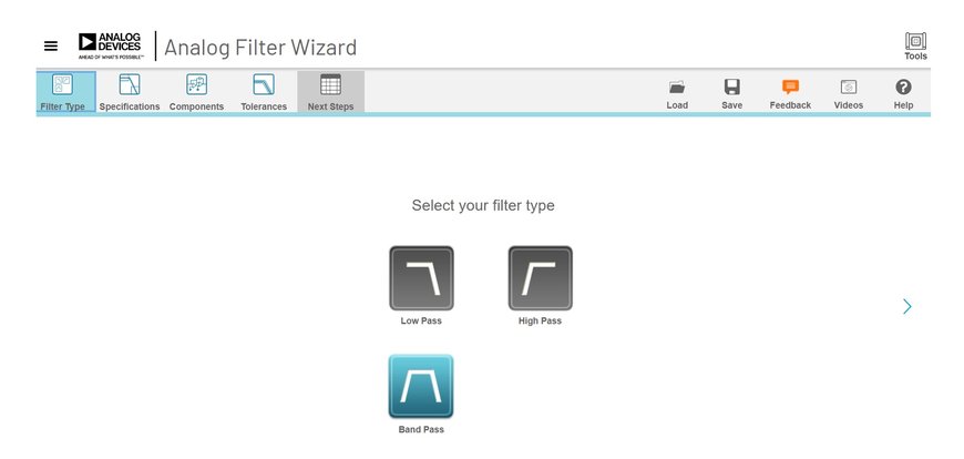
Figure 1 Filter type menu
Utilising free software tools like Analog Filter Wizard and LTSpice, both from Analog Devices, electronics engineers can now design and simulate the behaviour of a filter circuit before committing to building it in the lab or applying it in a test application.
The Design Challenge
The frequency of human speech is approximately between 300Hz and 3kHz. The challenge is to design a bandpass filter (BPF) that will allow signals within this range (the passband) to pass through the circuit while rejecting frequencies outside this frequency range (the stopband). A practical application for this filter is in the telephone system to band-limit the signal before it is digitized using an Analog-to-Digital Converter (ADC).
Building the Circuit
First, start the Analog Filter Wizard tool and select a Band Pass Filter from the choice of options (Figure 1).
Next, open the ‘Specifications’ tab to display a user-friendly graphical user interface (GUI) that allows the engineer to input filter specifications and then plots a graph of the corresponding filter frequency response. For this example, the values shown in Figure 2 generate a frequency response that closely matches the desired filter behaviour.
The passband is defined as the range of frequencies for which the output signal is at least 70% of the magnitude of the input signal and is indicated by the blue shaded area between the two -3dB ‘corner’ frequencies. The filter ‘roll-off is specified to be -40dB/decade which means signals whose frequencies are 10 times higher (or lower) than the two corner frequencies of 300Hz and 3kHz respectively, are attenuated (reduced in magnitude) by a factor of 100.
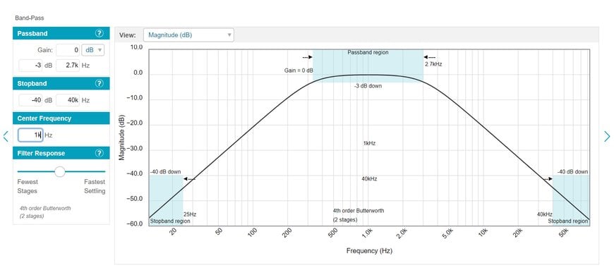
Figure 2 BPF frequency response
On the ‘Components’ tab, the elements required to build the filter are displayed. There is the option to add the voltage levels the circuit will use and select custom component types (resistors, capacitors, op-amp), or simply accept the default components selected by the tool.
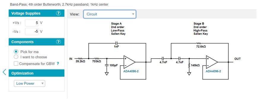
Figure 3 BPF Circuit components
The circuit configuration shown is for a fourth order Butterworth filter which comprises of a second order low-pass Sallen-Key filter and a second order high-pass Sallen-Key filter. In combination, they provide the desired bandpass frequency response.
Using the ‘SPICE Only’ function (under the ‘Next Steps’ tab), engineers can download the software files needed to simulate the circuit using the LTSpice simulation tool, which can be downloaded from Analog Devices’ website.
Define Input Signals
Figure 4 shows the LTSpice schematic shown after the ‘TransientAnalysis.asc’ file (provided by Analog Filter wizard) is opened. The two second order filter stages, power supplies (V2, V3) and input signal source (VIN) are clearly visible.
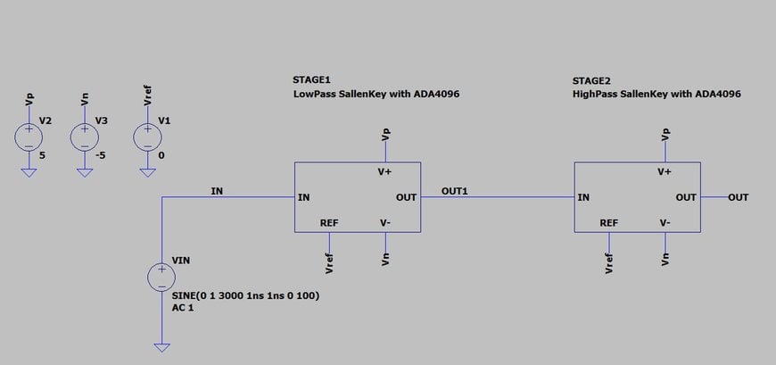
Figure 4 LTSpice BPF simulation schematic
Designers can quickly perform two types of simulation to verify that the filter design behaves as specified
- Transient Analysis
- AC Analysis
The transient analysis simulates the filter behaviour for a real-world time domain signal with a specified input voltage and frequency. The maximum input voltage must be within the operating voltage of the op-amps chosen.
AC analysis simulates the filter behaviour across the full range of possible input signal frequencies.
Simulating the Circuit and Examining the Output
For the transient analysis, the input signal is a 1V (peak) sine wave with a frequency of 1kHz. Figure 5 demonstrates that the signal passes unattenuated through the filter since the input (green trace) and output signal (blue trace) are almost indistinguishable. This behaviour is expected since 1KHz lies within the filter’s passband.
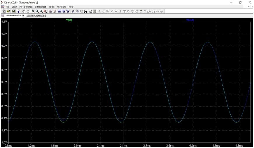
Figure 5 1KHz time domain signal passes unattenuated through the filter
Re-running the same simulation for an input signal with a frequency of 30kHz (Figure 6) shows the output signal to be almost 0V – again this is the expected behaviour as this frequency is outside of the passband (stopband).
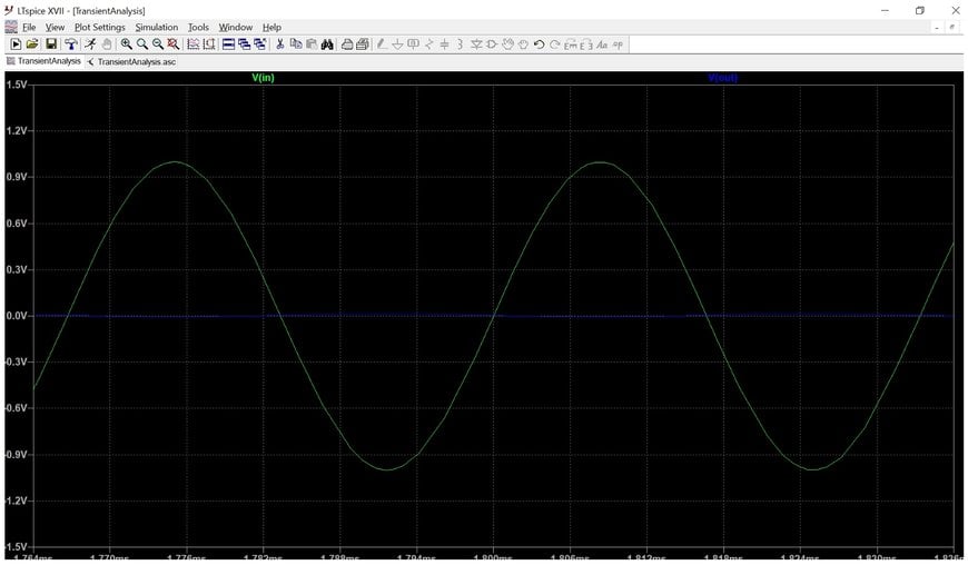
Figure 6 Filter rejects a 30KHz time-domain signal
The testbench schematic for the ‘ACAnalysis.asc’ file downloaded from Analog Filter Wizard is shown in Figure 7.
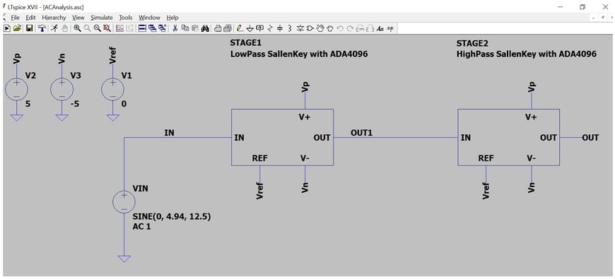
Figure 7 LTSpice AC analysis testbench
Figure 8 shows the frequency response of the filter generated by the AC analysis which closely matches that shown when specifying the filter performance in Analog Filter wizard (Figure 2).
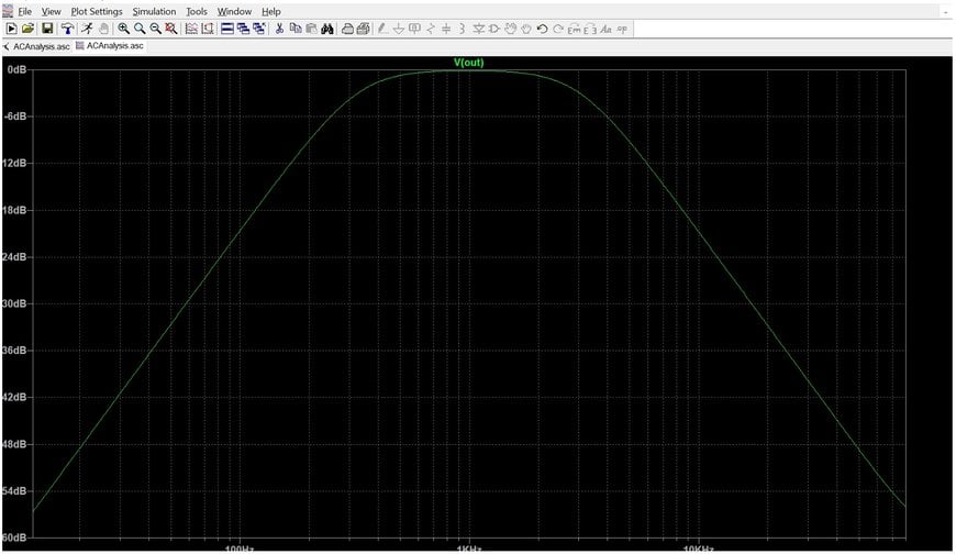
Figure 8 BPF filter frequency response
Conclusion
Throughout this four-part series of articles, our goal has been to increase awareness of the shortage and need for electronics engineers with analog design skills. We reviewed the basics of analog filter design and the tools that electronics engineers use to do their job. Far from being a design principle that relies on the subjective insight of the individual engineer, analog circuit design has evolved into a highly structured methodology, greatly simplified by the availability of advanced hardware and software tools that automate tasks previously requiring time-consuming manual calculations.
Hopefully, any young engineers reading this will to look at analog circuit design in a new light, and see it as a highly valued skillset and a rewarding career option.
www.mouser.com
