
electronics-journal.com
19
'22
Written on Modified on
A Guide to DC-DC Converter Design Basics
Most electronic equipment incorporates DC-DC conversion in some form. The switched-mode technique is an efficient solution which enables step up and step down in voltage as well as isolation, with small magnetics. This article gives a broad review of the technology and some commercial implementations.
By Ann-Marie Bayliss, Senior Product Marketing Manager, Murata
John Quinlan, Strategic Technical Marketing Manager, Murata
DC to DC conversion has been a challenge to system and product designers, starting in a major way when Edison lost out to Westinghouse in the ‘War of the currents’ in the late 19th century. Distributing AC at increasing power required ever-higher voltages to keep currents low and cables of reasonable size, but this could easily be achieved with transformers. DC could only be stepped up at the time with unwieldy motor-generator sets so the rest is history, Westinghouse won and AC distribution became the standard for the 20th century.
The last century was also the beginning of the age of electronics, which overwhelmingly requires DC for its components, so conversion from the AC distribution voltage to DC became necessary. But what DC? Circuitry can require anything from sub 1V for a processor to several kV for the magnetron in a microwave oven, sometimes together. If the rails required need to be accurate with changes in load and AC line, active regulation circuitry is also needed. Early equipment used 50/60Hz transformers to drop the AC to lower voltages, which could then be rectified, smoothed to DC and regulated down to a lower voltage by a ‘linear’ series transistor, but when load, line and tolerances are taken into account, the power taken from the AC line is around twice the load power, worst case. The transformer is also large, heavy and expensive so the arrangement is far from ideal. If a system DC rail needs to be stepped up in voltage, there is no ‘linear’ way to achieve this.
Switched-mode conversion solves the problem
The practical solution to efficient DC down- and up-conversion is the ‘switched-mode’ technique. When isolation is not needed, ‘buck’ and ‘boost’ converters or derived variants are used. The buck effectively ‘chops’ the input DC at high frequency so that its average is lower and then smooths the resulting waveform with an LC filter. The ‘chopping’ transistor is either fully on or off, in both cases dissipating little power and the output voltage is set by the transistor switching duty cycle. The boost converter operates a little differently – the chopping alternately stores energy in the inductor magnetic field, then releases it. Energy can be released at any chosen voltage, higher than the input. Other circuit arrangements such as the simple buck-boost and Ćuk can produce voltage inversion, while the SEPIC, ZETA and others can produce positive output voltages lower or higher than the input.
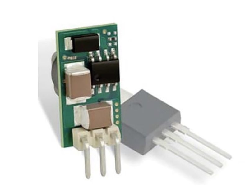
An example of Murata’s 78SR series [1] buck is shown in . The module has an input range of 7.5V to 36V for an output of 3.3V at 0.5A. At full load and 12V input it achieves 83% efficiency, dissipating about 0.7W. It is pin compatible with the popular ‘78xx’ series linear regulators which would dissipate a stressful 4.35W under the same conditions requiring substantial heatsinking.
While this through-hole part can change out an existing linear regulator for a boost in efficiency, better performance still is achieved by surface mount ‘Point-of-Load’ DC-DC modules with land-grid array footprints. The MYMGA series from Murata for example [2], achieves 94% efficiency at its full load current of 4A (5V version). This is all in a package 9mm x 10.5mm x 5.5mm high.
At high power, ‘multiphase’ bucks spread the component stresses across duplicated switches and inductors, driven in two or more phases with common input and output capacitors. For best efficiency, bucks also use ‘synchronous rectification’ where the rectifier diode with its fixed voltage drop is replaced by a low on-resistance MOSFET.
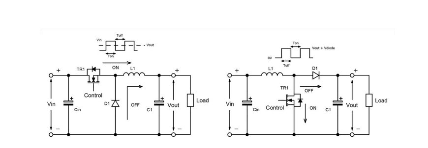
The buck and boost DC-DC converter outlines
Isolation is often required
Simple buck and boost converters do not provide galvanic isolation – their input and output grounds are connected. Often, that link needs to be broken to allow the output to ‘float’. This could be because the input is referenced to an unsafe voltage, to prevent circulating ground currents, or simply so that the output can be configured as a negative voltage by grounding the positive. The equivalent isolated topologies to buck and boost are forward and flyback converters, which can be viewed as converting the inductor in each case into a transformer so an isolated winding can provide the DC output. Note the specific phasing of the transformer windings.
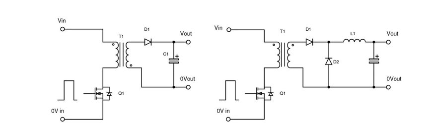
Flyback (left) and forward (right) converter outlines
Isolated DC-DC converters are more difficult to fully regulate as the output voltage has to be sensed and an error signal passed back across the isolation barrier to the primary to control duty cycle. Sometimes regulation is not necessary however; if the input DC is constant, only load variations affect the output, which might only change by a few percent, which is often acceptable. One of the largest applications for small isolated DC-DC converters is to provide power for isolated data interfaces where regulation is not critical. When the input DC varies, ‘semi’ regulation can be used, sensing a primary winding on the transformer as an analog of the output, but for best accuracy, the output voltage is sensed directly and an error signal passed to the primary, typically through an optocoupler.
When isolation is required for safety reasons, the spacings and insulation arrangements are complex. Creepage, clearance and distance through solid insulation necessary depends on the level of protection required (basic, double or reinforced, for example) and other parameters such as environmental pollution degree, over-voltage category of the input and even altitude. The application sets the standards applied, with patient-connect medical for example, requiring larger separation distances than industrial. There can be confusion about stated isolation rating; parts are often promoted with say, 3kVDC test in production, which might seem adequate for isolation of 230Vac.
However, this is only a one-off test voltage and does not guarantee that the part continuously withstands a high voltage. Users should look for an actual safety agency certification, the level tested to and the ‘system voltage’ it refers to. A DC-DC converter isolating a 230Vac mains referenced circuit from connections a user can touch in a home/office environment for example, might show ‘reinforced isolation/250Vac, maximum altitude 5000m’ according to EN 62368-1, the relevant safety standard in Europe.
Below image is an example of Murata’s NXJ series of an un-regulated buck-derived (actually push-pull) DC-DC converter which simply converts 5V to 5V with agency-rated isolation for medical applications. The product features a novel method of embedding the transformer core within the PCB stack, with the winding formed by PCB tracking and vias across many layers.
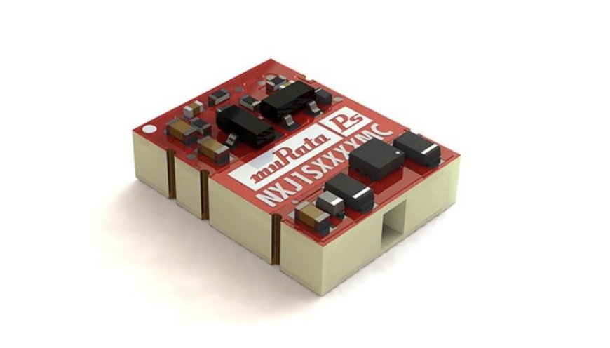
Murata’ NXJ series of surface mount DC-DC converter with agency-rated isolation
Resonant converters are efficient
The forward converter appears in many varieties with different pros and cons, often dictated by the application trade-offs of efficiency, cost and size for given power and voltage conversion ratings. For optimum efficiency, ‘resonant’ converters are often used, which ‘soft switch’, that is, change switch state while current or voltage is zero. This avoids the momentary spike in power dissipation if high voltage and high current occur together. There are many resonant topologies but a current favoured one for low to medium power is the ‘LLC’. The circuit applies pulses to an LC ‘tank’, typically just above its resonant frequency, with the pulses then passed as sine waves to a secondary load winding on the tank inductor, by transformer action. Regulation is achieved by varying the pulse frequency, which passes more or less energy through the transformer as a result of the increasing inductive impedance of the LC circuit with frequency, above resonance.
At high power, the stress on the LLC switching transistors becomes impractically high and then typically a ‘phase-shift full bridge’ topology is used. This is another resonant circuit in a four-switch bridge arrangement but operates at fixed frequency, with regulation achieved by varying the relative phase of the drive waveforms to each leg of the bridge. This technology is utilised in Intermediate Bus Converters such as the DRQ series from Murata.[5]
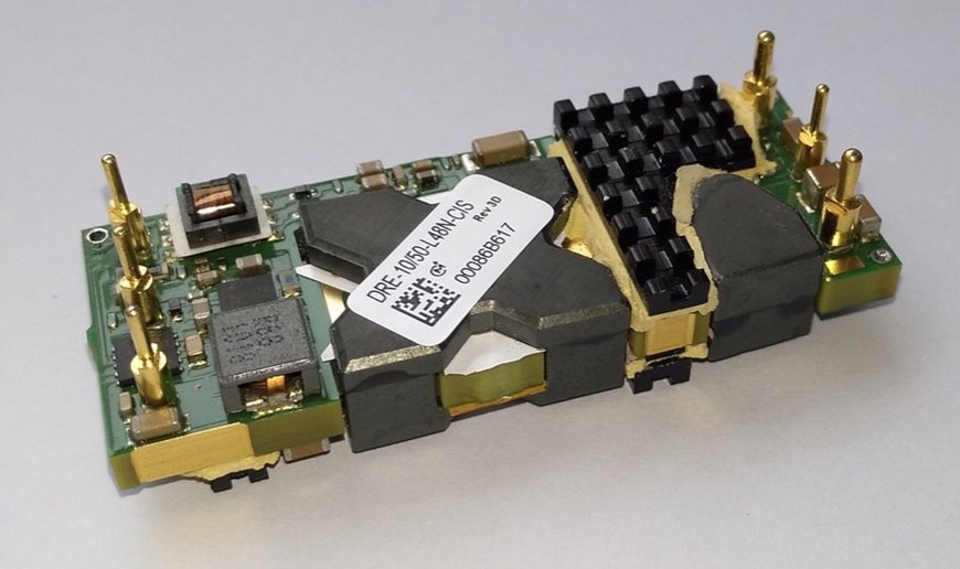
Murata’s DRE range
Switched-capacitor DC-DC converters need no magnetics
It is not necessary to use an inductor or transformer in a non-isolated DC-DC converter; switched capacitor arrangements can be used which charge capacitors in series or parallel then set them in parallel or series respectively to step down or up voltages respectively, in discrete multiples. Previously, switch and diode drops have limited the efficiency attainable but with modern MOSFETs and synchronous rectification, 96%+ can be achieved at 72W such as Murata’s Psemi novel switched capacitor technology [3]. There is typically no active regulation and the step up or down is in a fixed ratio, 3 or 4 in [3] but the technique, without an inductor lends itself to modern fabrication methods and low-profile products.
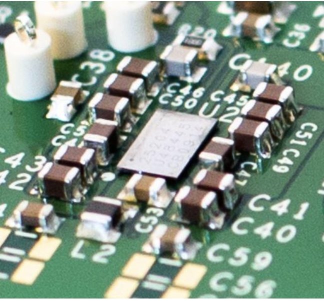
Murata’s Psemi switched capacitor technology
Cell-phones require highest efficiency power conversion
Lower-power non-isolated DC-DC converters find a home in many commonplace electronic items such as cell-phones, where maintaining battery run-time is important and is facilitated by high efficiency of all power conversion stages. Converters that regulate an output with the input higher than, or lower than the output voltage are particularly valuable as a battery loses charge and its output voltage drops. Such converters are often classified as ‘buck-boost’, although strictly this gives a negative output which is not always useful. The SEPIC converter mentioned before, is a popular choice to provide a positive voltage with the input above or below the output. Q1 in the schematic operates as a synchronous rectifier. L1 and L2 can be separate inductors or wound on the same core.
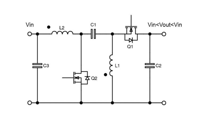
The SEPIC converter operates with input voltage above or below the output
Ultra-Wide DC Input Range Converters.
Having a single DC-DC converter that can operate from a multitude of battery voltages, can simplify applications where the manufacturer of the equipment is uncertain which battery source will be used by the customer, for example in railway applications the battery can range from 24V up to 110V depending upon the manufacturer of the locomotive and the geographical region. Murata’s IRH250 / IRQ150 satisfy this challenge with a DC voltage Input range of 16V – 160V DC.
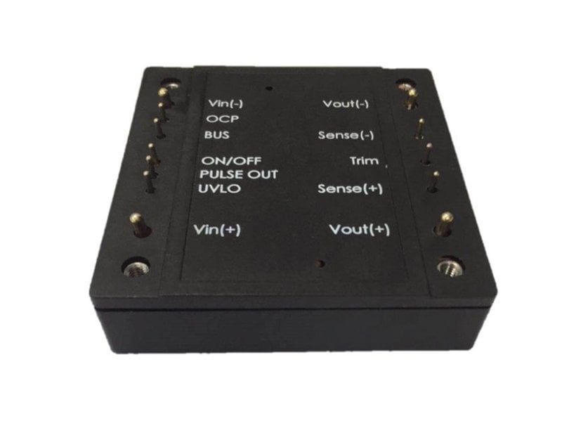
Murata’s IRH250 ultra-wide DC Input range converters.
Automotive requirements are severe
Small DC-DC converters in automotive equipment can be subject to harsh environmental and electrical stress. The automotive AEC-Q qualification test requirements are not generally applicable to power converters so they are often classified as ‘multi-chip modules’ to AEC-Q104. The manufacturer of the device must also have certification to TS 16949 for their quality management system, above and beyond the familiar ISO 9001 standard. The NXJ series from Murata in is an example of an AEC-Q104 -qualified part.
This article has necessarily been a ‘whistle-stop’ tour of the subject of DC-DC conversion but hopefully has shed some light on the design types, their performance capability and their applications.
References:
[1] https://www.murata.com/en-us/products/productdetail?partno=7803SR-C.
[2] https://www.murata.com/en-us/products/productdetail?partno=MYMGA5R04RELA5RA
[3] https://www.murata.com/en-eu/news/power/dcdc/2021/0419
[4] https://www.murata.com/en-us/products/productdetail?partno=IRH-12%2F21-W80PB-C
[5] https://www.murata.com/-/media/webrenewal/products/power/datasheet/drq-11_4-88-l48.ashx?la=en-us&cvid=20200224045920000000
www.murata.com
