electronics-journal.com
03
'22
Written on Modified on
Rutronik ABU Presents Smart HV-eFuse as a bodyguard in the HV architecture
Faster time-to-market through ABU reference design for high-voltage switches with series proximity.
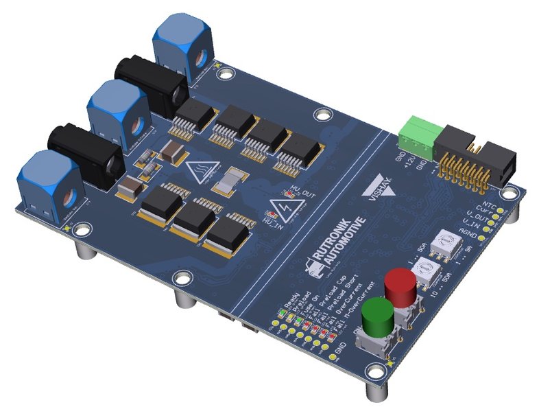
After initial successful tests, the reference design of the High Voltage Circuit Breaker (HVCB; high-voltage (HV) switch) from the cooperation between the e-mobility specialists of Rutronik's Automotive Business Unit (ABU) and Vishay's Automotive Division has been further optimized. Greater robustness and further matured proximity to series production characterize the 2.0 version (Fig. 1). The housing, created in a 3D process, was also adapted to the new design. The semiconductor solution replaces previous options that used mechanical relays. With this innovation, Rutronik ABU offers a future-proof solution that switches off the load very quickly and very safely in the event of a fault, such as a short circuit or overvoltage. This makes HV switches an indispensable link within an HV architecture of modern Battery Electric Vehicles (BEV).
In next-generation electric vehicles, up to three different voltage levels are identified:
The 12V electrical system for small actuators and all control devices, 48V for larger power consumers such as water pumps, EPS or radiator fans, and the 400 to 800V electrical system containing the battery pack and the largest consumers such as the inverter, high voltage heater, OBC, HV/LV DCDC and HVAC. The high-voltage range in particular requires the highest level of safety and reliability for all installed components. HV applications with higher voltages such as 1000V are also already under development. An adaptation of the reference design to higher voltages is also possible.
The BEV of the future requires technologies of tomorrow
Until now, mechanical relays have been used for this protective measure. However, these have a number of disadvantages: Arcing, which can occur when switching under load, permanently damages the relay and thus ensures premature aging. High switching losses result from the relatively slow switching behavior. Accordingly, more heat is generated, which may require additional active cooling should a fault occur in an auxiliary unit. The solution to this is an intelligent, resettable and low-loss HV switch.
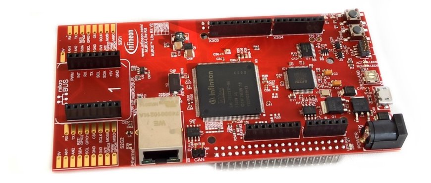
In terms of circuitry, the HV circuit breaker consists of an isolated 800V power stage with 12V measurement and evaluation electronics and an AURIX TC375 Lite Kit (Fig. 2). The concept of the HVCB is realized in the switching stage with high-performance semiconductors of the latest SiC generation from ROHM, galvanic isolation of the measurement channels, high-precision shunts, new optocouplers, and all protective components from Vishay. In addition, a second-generation AURIX microcontroller from Infineon controls the device.
For circuits up to 40KW
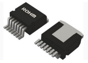
With ROHM's 1200V SiC MOSFETs in SMD package and a precisely tuned control via a SiC gate driver (Fig. 3), the HVCB is able to switch powers of up to 40kW. Statically, the resulting power loss reaches approximately 15 W. The resulting heat can be passively dissipated at room temperature (25°C). Thus, the innovative concept exceeds the requirements of premium OEMs. The values of the dynamic switching behaviour are still being determined in the laboratory.
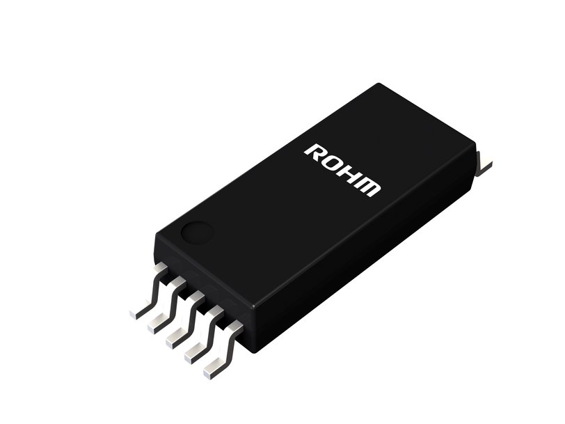
The HVCB has a pre-charge path that allows pre-charging capacitive loads via a SiC MOSFET (Fig. 4), two series-connected pre-charge resistors and an implemented pre-charge mode (25ms & 250ms). Here, the HVCB checks after the defined times if corresponding voltage thresholds have been reached, thus preventing a possible overcurrent when switching on. It is possible to connect external precharging resistors in parallel via two sockets in addition to the fixed precharging resistors. This allows an adjustment of the precharging resistor depending on the capacitive load. The galvanically isolated SiC driver BM61S41RFV from ROHM realizes the control of the main MOSFETs. A galvanically isolated optocoupler with phototransistor output drives the precharge MOSFET. The maximum load current of the switch can be set either via the microcontroller or in stand-alone mode individually via two rotary switches.
High-quality components for safety-relevant automotive applications
When selecting the integrated components, innovation, robustness and dielectric strength have a particularly focus: The power stage features two high-precision shunts from Vishay, characterized by their extremely accurate measurement of the battery current. In order to be able to measure also a possible current return, the measurement is carried out bidirectionally. The current and voltage measurement signals are transmitted galvanically isolated (floating measurement), processed by measurement signal amplifiers and passed on digitally to the microcontroller. The HV switch thus acts "smart". The new VOA300 linear automotive optocouplers from Vishay (Fig. 5) provides the galvanic isolation from the 12V side. These feature a large coupling factor and high bandwidth, are reflow solderable according to Jedec standard J-STD-020, and form a very cost-effective solution that is not susceptible to interference. The previously mentioned phototransistor-output optocoupler is Vishay's VOMA617A.
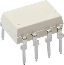
Eight high-voltage MLCCs from Vishay, two of which are connected in series, realise an impedance coupling of the voltage supply of both the measurement signal amplifiers and the SiC driver and optocouplers on the HV side. This decouples the high DC voltage of the high-voltage side from the low-voltage side and still enables the supply of the components on the high-voltage side. This supply includes a push-pull driver stage with 50 kHz. Due to placement of the HVCB close to the respective load, the line inductances turn out to be low. Nevertheless, the HVCB now has a parallel snubber circuit to prevent voltage spikes when switching this inductive load. Switching of large inductive loads, such as motors, is not yet intended.
The AURIX board is linked via cable connection (I²C) and can output the processed measured values after successful connection via an already implemented software. An existing CAN interface on the AURIX board realizes the configuration and readout of measured values of the HVCB with AURIX control.
Precise measurements, diagnostic function and protective measures
In addition to the precise current and voltage measurements, the concept also has a diagnostic function and further protective measures, such as over-current detection with adjustable threshold (digital in the software or analog via rotary switch) and a MOC (Massive OverCurrent) detection with lower tripping time for very high short-circuit currents. Input & output transient protection as well as additional TVS diodes for power supply protection complement it further.
Ratiometric thresholds do the monitoring of input and output voltage, which thus also allows the use for 400V systems. To avoid voltage fluctuations in the drive path of the SiC MOSFETs during power-up, a new polymer tantalum capacitor (T51 series from Vishay) buffers the SiC driver for the main MOSFETs. The temperature monitoring is now no longer analog via an NTC and galvanically isolated thermal bridges, but digital via an IC with PWM output. An AD converter evaluates the measured values directly on the HVCB board. Thus, the communication to the AURIX board is purely digital and less susceptible to interference. In addition, the reference design has a status display with LEDs as well as two buttons for manual control. New features are additional LEDs for displaying the applied high voltage on the input and output side as well as an EEPROM for local storage of measured values. This local memory enables an event log, which facilitates the readout and operation of the HVCB.
Optimizing time-to-market and meeting the highest demands
By developing reference products and offering new services that meet the future requirements of upcoming electric vehicle platforms, Rutronik ABU is redefining the term "design service" in distribution. Rutronik provides the reference design of the HV switch free of charge to selected tier-1 customers who are leaders in the automotive market. This also includes comprehensive documentation and a complete Bill of Material (BOM) with all components selected by ABU experts. This enables fast and high-quality implementation of a state-of-the-art circuit concept in future projects.
For more information : www.rutronik.com/internet-of-things/automotive/
www.rutronik.com
Author: Bernd Wondratschek, Field Application Engineer ABU at Rutronik Elektronische Bauelemente GmbH.

