
electronics-journal.com
20
'20
Written on Modified on
New visions with polarisation
Polarisation imaging can reveal information on physical properties such as stresses in plastic or glass. STEMMER IMAGING polarisation expert Jan Sandvoss gives us an insight into this powerful technique and its possibilities.

Jan Sandvoss: In order to gain a deeper understanding of how polarisation cameras work, you need to take a closer look at the physical basics. Light is defined by a propagating electromagnetic transverse wave, consisting of oscillating electric and magnetic waves that are perpendicular to each other and the direction they are travelling in.
Polarisation is defined by the oscillation plane of the electric wave. Light is typically not polarised, meaning that all directions of electric waves have the same probability. If there is only one direction of oscillation, we talk about linear polarised light. If the phase of the electric and magnetic fields is not the same, then the wave is said to be elliptically polarised.
If the waves are 90 degrees (a quarter wavelength) out of phase, we talk about circularly polarised light. This applies to the entire electromagnetic spectrum including ultraviolet light (UV), visible light with wavelengths between 440 and 650 nm, near infrared light (NIR) and shortwave infrared light (SWIR).

Jan Sandvoss
What is the main difference between unpolarised and polarised light?
Jan Sandvoss: Unpolarised light consists of lots of waves oscillating in different directions. Examples of this would be incandescent bulbs or sunlight. Using this type of illumination has a major downside in machine vision applications: Especially when inspecting objects with shiny surfaces it is practically impossible to avoid reflections in certain areas.
Polarised light, on the other hand, means that all the waves emitted by a light source have the same polarisation and correspond in the direction of the electric fields. This means that the clever use of polarised light can filter out unwanted reflections. In certain cases, this can facilitate and improve the inspection of optical properties on objects.
Can you give us some typical application examples?
Jan Sandvoss: This technology can solve a number of interesting applications. In general, various surface characteristics can change the polarisation state of light, for example, the surface properties of objects such as roughness, scratches, dents or coatings, but also other physical properties such as mechanical stress or birefringence. Especially when inspecting shiny, specular or reflective surfaces such as film, metal or glass, polarisation images improve machine vision processes such as easier detection of scratches or robust reading of codes on multi-layer films.
Inspection of shiny and reflecting surfaces
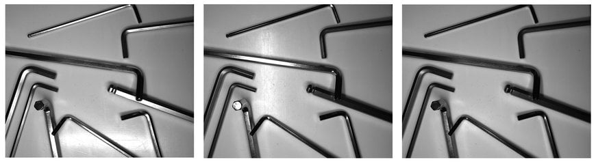
By combining reflection-free parts of the images into a single image, it is possible to merge areas that are easy to evaluate and thus simplify the image processing and identification of the objects and their position on this synthetic image.
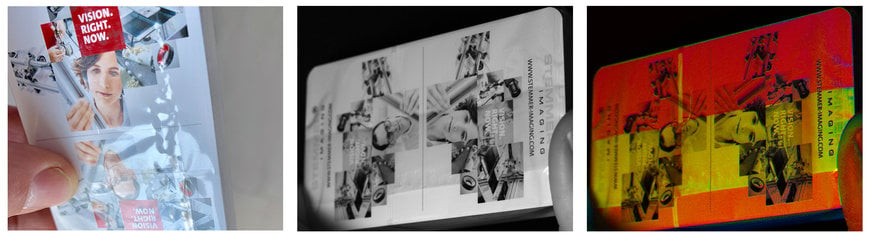
Film inspection of card deck tear tabs
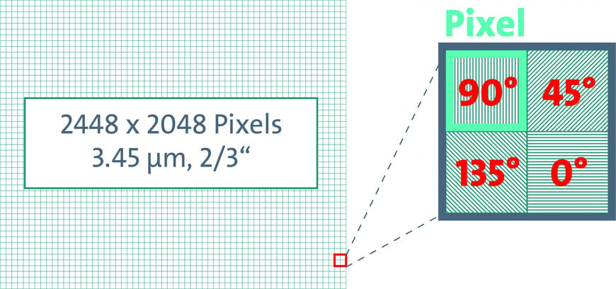
Jan Sandvoss: In autumn 2018, Sony introduced the IMX250MZR CMOS sensor whose polarisation functions are integrated at a pixel level, and can solve a variety of imaging tasks. Since then, the topic has considerably gained momentum in the field of machine vision. This sensor is able to filter light at four angles, 0°, 45°, 90° and 135° and only transmit the part of the light that is in the same orientation as the respective polariser.
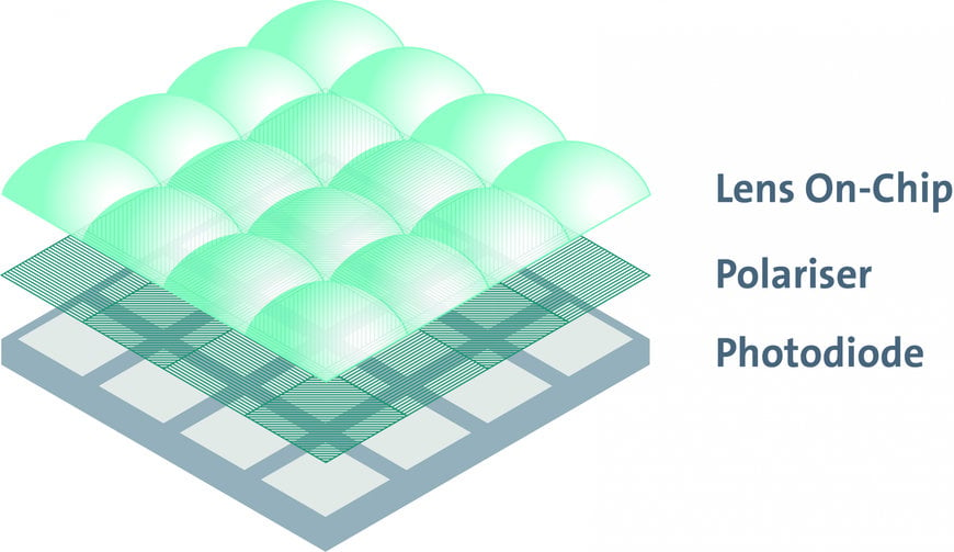
For each calculation unit, the Sony sensor uses four nanowire grids oriented at the angles mentioned earlier. The polariser is located as a layer between the photodiode and the on-chip lens. The smart sensor design reduces the unwanted crosstalk effect, which occurs when light at a polarised angle is misdirected into an adjacent pixel.
So, various camera manufacturers have probably used this sensor for designing polarisation cameras?
Jan Sandvoss: Exactly, there are already a number of industry leading camera manufacturers who have introduced products using this technology. STEMMER IMAGING cooperates with trusted partners including Allied Vision, JAI and Teledyne Dalsa.
Just like with area scan cameras, four polarisation filters with different polarisation angles have been implemented for direct acquisition. However, for both area scan and line scan polarisation cameras, it is also possible to define other "virtual" polarisation angles by interpolation from the four main directions in order to achieve the optimum alignment for different tasks.
How do images from polarisation cameras and images from conventional cameras differ?
Jan Sandvoss: The so-called Stokes vector is the basis of polarisation images. The polariation of light can be quantitatively specified by using this vector, which consists of four values that define the direction and magnitude of an electromagnetic waves polarisation and thus the degree of the linear, circular or elliptical polarisation.
After recording objects with a polarisation camera, it is possible to generate images which represent the first three Stokes’ parameters. In a further step, the Stokes’ parameter images can be combined into single images, in which the pixel’s intensity represents the Degree of Linear Polarisation (DoLP) and the Angle of Mean Polaisation (AoMP). For better visualisation, these DoLP and AoMP images can also be mapped to the HSV colour space. An example of this could be to better visualise the stresses in the structure of plastic objects. This type of visualisation also simplifies subsequent image evaluation.
What equipment do you need to take polarised images?
Jan Sandvoss: In addition to a polarisation camera, suitable lighting and lenses are required on the hardware side to enable high-quality images. Of course, as with any machine vision system, cables are required to transfer the images to the processing computer.
Some software environments, such as the Common Vision Blox software library developed by STEMMER IMAGING, already contain suitable tools for evaluating polarisation images.
Polarisation cameras can reveal the light’s third dimension, thus making it usable for machine vision. This means that the technique can be used to detect properties or defects that simply could not be seen using any other imaging technique.
www.stemmer-imaging.com
