
electronics-journal.com
14
'26
Written on Modified on
Dual-Die Magnetic Motor Position Sensors for ASIL D By-Wire Applications
TDK introduces Micronas HAR 3025 with stray-field compensation to ensure fail-operational commutation in redundant automotive actuators.
www.tdk.com
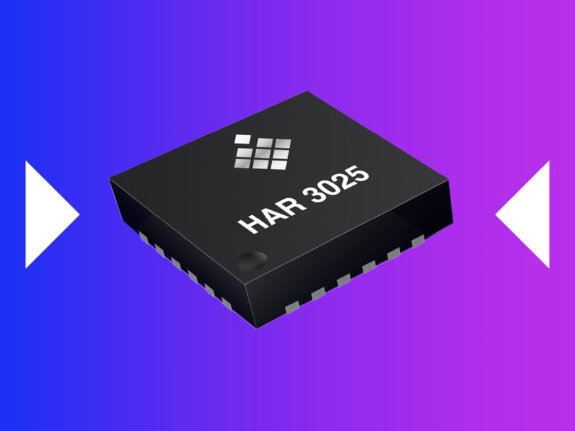
Safety-critical automotive actuators require continuous, high-integrity rotor position telemetry to maintain vehicle stability during electrical, mechanical, or magnetic disturbances. TDK Corporation has developed the Micronas HAR 3025, a dual-die, stray-field robust magnetic angle sensor engineered to deliver redundant analog sine and cosine feedback for mission-critical electric power steering, steer-by-wire, brake-by-wire, and high-voltage traction motor systems.
Electromagnetic Interference in Modern Vehicle Electrification
The transition toward steer-by-wire and electromechanical braking architectures eliminates traditional mechanical linkages between the driver and the chassis. In these fail-operational systems, the motor control unit cannot simply shut down when an anomaly occurs; it must continue functioning without interruption. Concurrently, the electrification of powertrains places position sensors in close physical proximity to high-current busbars, inverter switching stages, and traction motors. These power electronics generate severe DC and AC magnetic stray fields that can distort conventional magnetic angle readings and degrade commutation precision.
To maintain positioning fidelity without adding the mass, packaging volume, and bill-of-materials cost of external magnetic shielding or oversized target magnets, sensor hardware must integrate native common-mode rejection. Furthermore, autonomous driving Level 3 and above mandates dual-channel hardware independence to satisfy the strictest functional safety criteria without expanding physical housing dimensions.
Stacked-Die Sensor Architecture and Sensing Principles
The Micronas HAR 3025 addresses these packaging and reliability constraints by integrating two fully independent dies vertically stacked within a single 4-by-4 millimeter QFN24 package equipped with wettable flanks for automated optical inspection. Because the stacked dies share coinciding centers of magnetic sensitivity, both channels intercept the identical magnetic field vector from a simple two-pole target magnet positioned in an end-of-shaft layout. This physical alignment allows the electronic control unit to conduct real-time plausibility checks without mathematical offsets caused by lateral die displacement.
Each individual die features an array of six horizontal Hall plates combined with integrated differential signal processing. In accordance with ISO 11452-8:2015 requirements, the differential topology measures the gradient of the target magnet field while canceling out homogenous external magnetic stray fields. The device evaluates magnetic flux densities across a broad range from plus-or-minus 5 millitesla to plus-or-minus 250 millitesla.
Functional Safety Implementation and Fault Handling
Developed as a Safety Element out of Context in compliance with ISO 26262:2018, both dies within the sensor independently fulfill ASIL D safety metrics. The physical and electrical separation ensures that a malfunction on one die does not propagate to the other. If one channel encounters a fault condition, the second channel continues full-rate operation to preserve system-level fail-operational capability.
On-chip diagnostic blocks continuously supervise critical parameters, including internal clock stability, supply voltage levels, junction temperature, Hall signal processing integrity, configuration registers, and non-volatile EEPROM memory. Upon detecting an internal anomaly, the affected die transitions its analog outputs into a high-impedance state, enabling external pull-up or pull-down circuits at the microcontroller input stage to identify and isolate the error.
Analog Output Precision and Signal Conditioning
The sensor delivers high-speed contactless 360-degree angular measurements at rotational velocities reaching up to 60,000 revolutions per minute. Outputs are structured as ratiometric analog sine and cosine signals, available in either differential or single-ended configurations. The analog signal chain maintains low delay-time jitter, with root-mean-square values capped at 2 nanoseconds, supporting precise vector control and torque ripple suppression in brushless direct-current motors, permanent magnet synchronous motors, and AC induction machines.
Operating across a supply voltage range of 3.0 volts to 5.5 volts, the unit functions at junction temperatures between minus 40 degrees Celsius and 170 degrees Celsius, with ambient temperature ratings reaching 150 degrees Celsius. Static calibration at end-of-line testing yields a total angular error of 0.6 degrees or less, which can be further optimized to 0.1 degrees or less via dynamic microcontroller-level compensation algorithms.
Signal chain parameters—including gain, offset, zero-angle reference, orthogonality correction, and four selectable bandwidth limits ranging from 4.6 kilohertz to 70.5 kilohertz—are programmable directly through the output pins. This single-wire calibration methodology removes the need for dedicated programming pins. Commercial engineering samples of the sensor are currently available for automotive tier-one validation, with full-rate manufacturing scheduled to begin in the first half of 2027.
Additional Context:
This section details technical specifications and competitive benchmarking not included in the original product announcement.
The automotive motor position sensor market features several primary sensing topologies, including Hall-effect arrays, anisotropic magnetoresistive, giant magnetoresistive, and tunnel magnetoresistive architectures. In high-power x-by-wire applications, Hall-effect array sensors remain widely adopted because of their high magnetic saturation limits and proven stray-field compensation based on spatial field gradients, whereas unshielded magnetoresistive devices can saturate under strong external fields exceeding 2 to 5 millitesla unless equipped with specialized shielding or algorithmic correction.
In the competitive landscape of ASIL D redundant motor position sensors, the Micronas HAR 3025 competes directly with dual-die solutions such as the Allegro MicroSystems A33020 and A33230 series, the Melexis MLX90380 and MLX90423 family, and the Infineon XENSIV TLE5014 dual-die products. While solutions like the Allegro A33020 also incorporate stray-field immunity with digital and analog interfaces in surface-mount configurations, packaging approaches vary between side-by-side dual-die arrangements (such as TSSOP-16 packages) and vertically stacked dies (such as compact 4-by-4 millimeter QFN formats).
Stacked-die configurations offer an inherent mechanical advantage by eliminating the spatial parallax error between channels, ensuring that both sensing elements read identical magnetic field angles without phase-shift correction in firmware. Meeting ISO 11452-8:2015 Level 4 test conditions requires devices to withstand DC and AC magnetic fields of up to 4,000 amperes per meter (approximately 5 millitesla) across low frequencies without exceeding angular error limits. High output bandwidths above 50 kilohertz, paired with sub-microsecond group delays, have become the standard industry benchmark for high-speed traction motor commutation in electric vehicles to minimize torque ripple and power inverter switching losses.
Edited by Natania Lyngdoh, Induportals editor, with AI assistance.
www.micronas.tdk.com
