
electronics-journal.com
23
'20
Written on Modified on
How to select the right type of transformer
Anthony J. Kourtessis, Design Engineer, Signal Transformer
Introduction
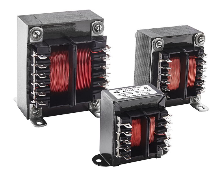
Transformers are common components widely used in many applications where an AC voltage needs to be modified or in some other way managed. The basic principle is relatively simple; the AC voltage going in is proportional to the AC voltage coming out based on the ratio of the number of primary and secondary windings. However, there is a lot more to understand about transformers and how they work. Here, we provide answers to some of the most common questions asked about transformers, in the form of a list of terms with definitions.
Choosing the right type of transformer begins with understanding that not all transformers are created equal. Here is a list of the most common types, and an explanation of how they differ.
Isolating transformer: Generally speaking, the primary and secondary windings of a transformer are only connected through mutual inductance, so they are naturally isolated from each other. An isolation transformer may take this a step further, by adding more resilient isolating materials to increase the amount of galvanic isolation. Isolating transformers might be used to increase the user safety.
Step-up/Step-down transformer: This describes the basic function of a transformer, based on the ratio of the windings. If the primary side has more windings than the secondary side, the output voltage will be proportionally lower than the input voltage. If the secondary side has more windings than the primary, the output voltage will proportionally higher. In both cases, the current available at the output will also change, such that the total power at the output matches the total power at the input, less any losses (see below).
Buck-Boost transformer: This is a type of transformer that compensates for voltage changes on the primary side by decreasing (bucking) or increasing (boosting) the voltage on the secondary side.
Autotransformer: Although it may sound like it operates 'automatically', autotransformer actually refers to a transformer that only has one winding. The primary and secondary are effectively formed from the same copper winding and it uses taps (see below) to select the output voltage based on the input voltage. An autotransformer can still step-up or step-down the input voltage, depending on how and where the input and output voltages are connected to the single winding.
Efficiency and regulation are two critical parameters to consider when specifying and selecting a transformer, so it is important to understand each one.
Efficiency: This is simply the ratio of the output to the input. In general, transformers are extremely efficient, which is one reason why they are used extensively. A transformer's losses are predominantly related to the losses in the iron core and in the copper winding.
Regulation: This figure describes how well a transformer can maintain its output voltage based on changes in load, even when the input voltage remains constant and steady. This is different to efficiency because it is load dependent.
Transformer design can vary based on the type of transformer (see above) but there are some commonalities, as explained below.
Taps: These are used to adjust the turn ration between the primary and secondary sides of a transformer. They are used to make small adjustments to the output voltage based on voltage variations present on the input side.
Phases: Each AC signal applied to the primary side of a transformer is referred to as a phase, which relates to its sinusoidal waveform as well as the phase difference between multiple phases. A three-phase transformer would have three primary sides and three secondary sides.
Y Configuration: This is one configuration for a three-phase transformer. It describes the shape of the transformer's winding, as it has three arms that join together at a single point, like a letter Y. It supports more voltages than a Delta configuration, which can be important when using more than one transformer in parallel or series (see below).
Delta Configuration: This is another configuration for a three-phase transformer. It describes the shape the transformer's windings make, as it has three arms that are connected at their ends, like a Delta (or triangle). It is more reliable than a Y configuration because it offers redundancy.
Windings: This is the term used to refer to any copper wire that is wound around the magnetic core. Most transformers will have at least two windings; the primary and secondary.
Inrush current: This is the amount of current the transformer draws at switch-on. The amount of inrush current is dependent on the phase of the AC input at the point of switch-on. Inrush current can exceed the maximum saturation current (see below).
Exciting current: This is the amount of current that flows in the transformer even with no load attached. As such, it can be seen as a resistive loss that is in phase with the input volage.
Saturation current: If the current flowing through the primary is too high, the core's flux goes into saturation. At this point, it cannot increase its output any higher.
Transformers are considered to be static electrical components and can offer a lot of flexibility in their use, as described here.
Connecting in series: It is possible to connect multiple transformers in series, where the primary sides are wired in series to split the total primary side voltage. As long as the maximum ratings for each transformer are observed, series configuration is possible.
Connecting in parallel: It is also possible to connect multiple transformers in parallel, where the primary sides are wired in parallel to share the total primary side voltage. As with wiring in series, it is important to remain within the rated voltage and current limits.
Connecting in reverse: This is not recommended, as it has an impact on the inrush and excitation currents and can cause safety circuits to trip.
Operating frequencies: A transformer is typically designed to operate at a specific frequency. Changing the frequency of the AC supply could require some derating, so that the maximum operating voltage isn't exceeded.
Grounding: If a ground terminal is included with the transformer, it should be connected in accordance with the local electrical regulations.
Conclusion
Understanding the principles of how transformers operate is a good place to start, but when it comes to specifying the right transformer, and its correct implementation, it makes sense to consult an expert. Signal Transformer has a wide range of transformers and high frequency magnetic solutions, as well as surface-mount transformers.
For more information, please visit: www.belfuse.com
