
Inverters – Getting the Right Voltage
Renewable energy must provide high-quality power if it is to become a suitable alternative to fossil-fuel sources. A smooth and ideally seamless transition from fossils to renewables, transparent to end-users is needed. Both types must be able to coexist.
Power Quality and Energy Efficiency
Renewable-powered generators, at the very least, must provide power at the correct voltage and frequency to supply the grid. There are some well known challenges for renewable energy sources feeding grids today: PV cells produce a very low DC output voltage, while the output of a turbine generator can contain frequency variations and harmonics.
These rough sources must be converted into grid-quality electricity with the highest possible efficiency while meeting all applicable standards for equipment connected to the grid. Ultimately, the utilities supplying power must satisfy the grid codes established by the appropriate operating authority, such as the national system operator.
The topology of the power-conditioning system has a meaningful effect on energy efficiency and grid-code compliance.
Solar Power Conditioning
An array of PV panels can range in size from small domestic systems to large solar farms of several megawatts. Conditioning of the DC output from the PV panel, including power-point tracking, can be implemented as a standalone DC/DC converter or as an integral part of the inverter that handles the transition from DC to AC suitable for connection to the grid. The inverter implementation can be as a microinverter at the panel level, or multiple panels, powering a string inverter. The implementation of a central inverter is an additional alternative.
The optimum solution can depend on factors such as the power rating, target cost, and any plans to scale the installation in future. Microinverters allow easy scaling, although the outlay can be relatively high with one inverter per panel. A centralised inverter, on the other hand, represents a single point of failure in the system and transmitting DC power through the array poses fire and safety risks.
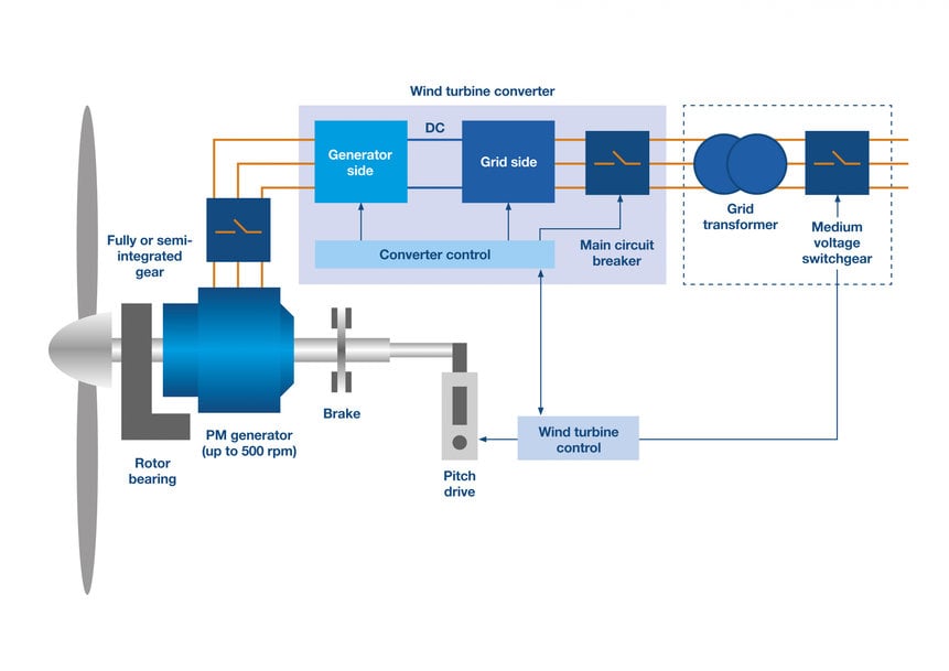
Wind Turbine Topologies Changing
Typical topologies used with wind turbines include doubly-fed (DF) generators and full-converter (FC) topologies. DF generators are widely used in onshore installations. The generators stater, directly connected to the grid, its rotor, connected through a converter/inverter network. In this arrangement, the generator output frequency matches that of the grid. Moreover, only about one-third of the generated power passes through the converter/inverter, which ensures low energy losses and allows the equipment to be smaller and of a lower cost. They are suitable for installations up to about 6MW.
In the FC case, the generator is completely decoupled from the grid using a converter/inverter that carries the full generated power. A fundamental advantage of this approach is the protection of the generator from disturbances on the grid. The FC system lends itself to the latest fault-tolerance requirements such as low-voltage and high-voltage ride-through (LVRT, HVRT).
These systems require the generator to remain connected during disturbances, caused by the connection and disconnection of large loads, and resulting in significant fluctuations in grid voltage. It is suited to applications up to the 10MW range.
Historically, wind generators have been allowed to disconnect from the grid during such events and attempt to reconnect at a later time. As the energy supply becomes more dependent on wind, this is not desirable and could lead to blackouts. Expectations are that full-converter systems capable of meeting the latest ride-through requirements, will be widely deployed for wind power in both onshore and offshore plants.
SiC and GaN Bring Efficiency and Robustness
Following the optimal topology, system efficiency is a crucial concern. The commercial availability of wide-bandgap power semiconductors, such as:-
- Infineon’s CoolSiC silicon carbide (SiC) trench MOSFETs
- Texas Instruments’ Gallium nitride (GaN) LMG341xR050 modules allow designers extra freedom to boost efficiency while also increasing greater power density.
- The Infineon CoolSiC MOSFETs include devices rated up to 1200V that allow high switching frequency and benefit from high immunity to parasitic turn-on. Infineon EiceDRIVER gate driver ICs simplify generating the asymmetric switching signals these devices require.
Modules Simplify Design with SiC and GaN
Modules are available that combine SiC MOSFETs with SiC Schottky barrier diodes in various configurations, such as Infineon CoolSiC modules and Rohm Semiconductor half-bridge modules.
These simplify design and significantly reduce switching losses compared to silicon IGBT modules of comparable ratings.
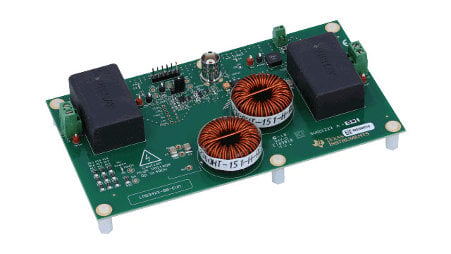
Texas Instruments’ LMG341xR050 is an integrated GaN power stage that combines a 600V MOSFET, driver, and protection features in a single module that simplifies circuit design and layout challenges. Unlike conventional MOSFETs, GaN devices have no intrinsic body diode, reducing energy losses during reverse conduction dramatically. Additionally, low input and output capacitance enhance switching performance while low EMI is another advantage of this technology.
Summary
Generating usable electricity from renewable sources is critically dependent on getting the right voltage, achieving this as efficiently as possible, while also meeting established standards for power quality and the performance of grid-connected equipment is a must. As the renewables revolution matures, these are changing, and engineers need to stay up to speed with the latest requirements and the technologies available to fulfil them.
www.mouser.com
